Free UK Delivery • 30-Day Returns • 2-Year UK Warranty

Motor Cable Megohmmeter Explained: A UK Buyer's Guide

Motor Cable Megohmmeter Explained: A UK Buyer's Guide
By Daniel Z.2026-07-2310 min read

Electrical motor failures cost UK manufacturing facilities millions of pounds annually in unplanned downtime and lost production. At the heart of most unexpected breakdowns is insulation degradation, either within the motor windings themselves or along the supply cables. Identifying these faults before they cause a catastrophic failure requires specialist diagnostic equipment, specifically a motor cable megohmmeter.

Unlike standard multimeters that measure basic continuity using low voltages, a megohmmeter applies high DC voltage to stress the insulation, revealing microscopic cracks, moisture ingress, and thermal degradation that would otherwise remain hidden. For UK plant maintenance teams, electricians, and industrial engineers, understanding how to select and deploy this instrument is critical for maintaining operational efficiency and complying with the Electricity at Work Regulations 1989.

Key Takeaways

  • A motor cable megohmmeter injects high voltages (up to 1000V) to accurately meansulation resistance in Megohms (MΩ) or Gigohms (GΩ).
  • Standard multimeters cannot detect insulation breakdown because their test voltages (typically 9V) are too low to bridge air gaps or moisture paths.
  • According to IEEE reliability studies, up to 51% of industrial electric motor failures stem from insulation breakdown.
  • Advanced diagnostics, including Polarization Index (PI) and Dielectric Absorption Ratio (DAR), are essential for assessing the true condition of motor windings over time.
  • UK regulations and BS 7671 require rigorous insulation resistance testing to ensure electrical safety and prevent fire hazards.

The Anatomy of a Motor Cable Megohmmeter

A motor cable megohmmeter is a specialised form of insulation resistance tester designed to evaluate the integrity of the protective sheathing around electrical conductors. In an industrial environment, electrical cables and motor windings are subjected to severe operating conditions. Vibration, extreme temperature fluctuations, chemical exposure, and physical abrasion constantly wear down the insulating materials.

When insulation degrades, electrical current begins to leak from the conductor to the earth, or between adjacent phases. This leakage current generates excess heat, which accelerates the degradation process, eventually leading to a dead short, a tripped circuit breaker, or a fire. A megohmmeter prevents this by acting as a high-voltage stress test. By applying a controlled DC voltage—usually 500V or 1000V for standard UK 400V three-phase systems—the instrument measures the tiny amount of current that manages to leak through the insulation. Using Ohm's Law (Resistance = Voltage / Current), the device calculates and displays the resistance value.

A high resistance reading indicates healthy insulation, whilst a low reading points to deterioration. For serious fault-finding, modern digital models offer vast measurement ranges. To understand why industrial applications require such broad measurement scales, you can review our comprehensive guide to 100G Ohm megger meters, which details the necessity of high-capacity testing in heavy industry.

Why Insulation Testing is Critical for UK Plant Maintenance

Maintaining electrical infrastructure in the UK requires strict adherence to safety standards, primarily the IET Wiring Regulations (BS 7671). The Health and Safety Executive (HSE) regularly highlights the dangers of poorly maintained electrical systems, noting that insulation failure is a leading cause of industrial electrical accidents.

Research published by the Institute of Electrical and Electronics Engineers (IEEE) indicates that 51% of industrial electric motor failures are directly caused by insulation breakdown or winding faults. Waiting for a motor to fail before taking action results in costly emergency repairs and halted production lines. Implementing a routine testing schedule with a motor cable megohmmeter shifts maintenance from reactive to predictive.

By logging insulation resistance values over months and years, maintenance engineers can plot a degradation curve. If a motor cable consistently reads 50 GΩ and suddenly drops to 5 GΩ during a quarterly inspection, the team knows intervention is required long before the insulation completely fails and causes an unplanned shutdown.

Essential Features of an Industrial Motor Cable Megohmmeter

Selecting the correct instrument for plant maintenance involves looking beyond basic continuity testing. Serious fault-finding demands specific capabilities that ensure accurate, repeatable, and safe measurements.

1000V Testing Capability

The test voltage must appropriately stress the insulation without causing permanent damage. The general rule for testing is to apply a voltage slightly higher than the system's normal operating voltage. In the UK, standard industrial motors operate on a 400V three-phase supply. Testing these systems with a 250V tester will not reveal high-resistance faults. A reliable motor cable megohmmeter must feature a 500V and 1000V output setting to accurately assess 400V cables and windings, forcing current across micro-cracks and moisture paths that a lower voltage would miss.

100GΩ Resistance Range

Older analogue testers often maxed out at 2000 MΩ (2 GΩ). While this is sufficient to determine if a cable is safe to energise today, it is entirely inadequate for predictive maintenance. Modern synthetic insulation materials, such as XLPE (Cross-linked polyethylene), possess incredibly high baseline resistance when new—often exceeding 50 GΩ. If your tester peaks at 2 GΩ, a brand-new cable and a severely degraded (but still functional) cable will both simply read ">2000 MΩ". A high-range instrument allows technicians to track the exact baseline and monitor subtle degradation over time. For a deeper dive into this specific feature, our analysis of high-range insulation testing provides extensive technical context.

Diagnostic Insights: PI and DAR

A simple spot-reading of insulation resistance can be misleading. Temperature variations and surface moisture can cause a perfectly healthy motor to yield a low resistance reading. To combat this, advanced testers utilise time-resistance methods, specifically the Polarization Index (PI) and the Dielectric Absorption Ratio (DAR).

These tests involve applying the voltage for a set duration and comparing the resistance at different time intervals (e.g., the ratio of the 10-minute reading to the 1-minute reading for PI). Because temperature remains relatively constant during a 10-minute test, these ratios cancel out temperature variables, providing a true picture of the insulation's condition. A low PI score strongly indicates moisture or severe dirt contamination within the motor windings. To fully grasp how to interpret these vital metrics, we recommend reading our dedicated guide on understanding PI and DAR testing.

Best Practices for Testing Motor Cables and Windings

Operating a motor cable megohmmeter requires strict adherence to safety protocols. High-voltage testing can be lethal if proper safe isolation procedures are ignored, and it can destroy sensitive electronic equipment if applied incorrectly.

Safe Isolation and Preparation

The absolute priority before connecting any testing equipment is proving the circuit is dead. Technicians must follow the UK's standard safe isolation procedure: lock off the supply, apply a warning tag, and use an approved voltage indicator and proving unit to ensure zero potential remains on the system. Once isolated, any variable frequency drives (VFDs), soft starters, or sensitive control electronics must be physically disconnected from the circuit. Injecting 1000V into a micro-processor-controlled drive will cause immediate and irreversible damage.

Phase-to-Earth Testing

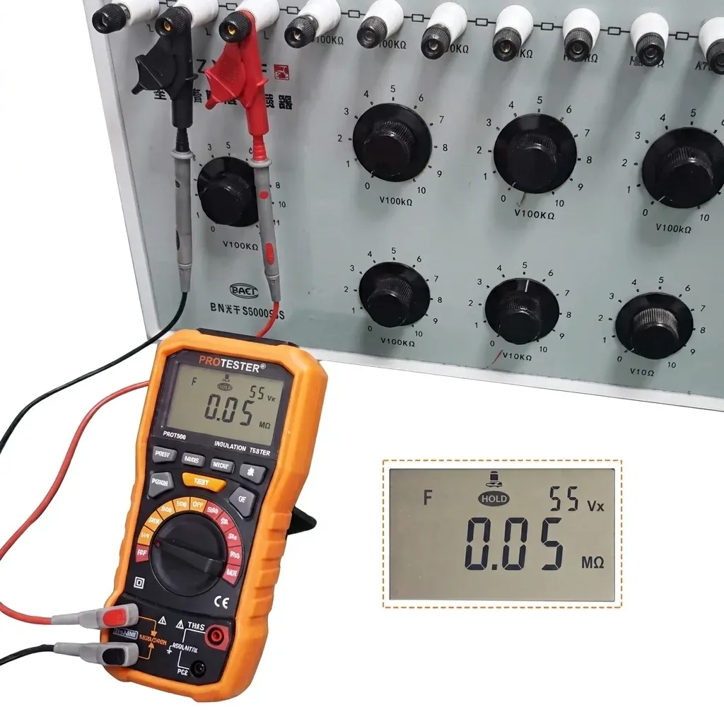
The most common test involves checking the insulation between the live conductors and the earth. Connect the negative (black) lead of the motor cable megohmmeter to a verified earth point on the motor chassis or the main earthing terminal. Connect the positive (red) lead to the first phase conductor. Apply the test voltage and hold it until the reading stabilises. Repeat this process for the remaining two phases. In a healthy system, all three readings should be exceptionally high and relatively balanced.

Phase-to-Phase Testing

Insulation can also fail between the individual conductors themselves, leading to a phase-to-phase short circuit. To test this, connect the instrument's leads across two distinct phases (e.g., L1 and L2, then L2 and L3, and finally L1 and L3). Again, the resistance values should be consistently high across all combinations.

Safe Discharging

Long cable runs and large motor windings act like massive capacitors, storing the high-voltage charge injected during the test. Disconnecting the leads immediately after testing leaves a lethal voltage sitting on the cables. High-quality diagnostic tools feature an automatic discharge function, safely bleeding the stored energy away internally while displaying the decaying voltage on the screen. Always wait for the voltage to drop to zero before touching the conductors.

Interpreting the Data: What Constitutes a Good Reading?

Acceptable insulation resistance values depend entirely on the operating voltage of the system and the specific standards governing the site. As a general rule of thumb derived from IEEE Standard 43, the minimum acceptable insulation resistance for a motor operating at 400V is 1.4 MΩ (calculated as 1 MΩ plus 1 MΩ per kilovolt of operating voltage). However, in modern UK industrial settings, a reading of 1.4 MΩ would be considered catastrophically low and indicative of imminent failure.

For newly installed XLPE cables or freshly rewound motors, readings should easily exceed 1000 MΩ (1 GΩ). If a previously healthy system drops below 100 MΩ, it warrants immediate investigation. This is where selecting the correct electrical insulation meter becomes crucial; the instrument must provide enough granularity to detect the drop from 500 MΩ to 100 MΩ accurately.

Serious Fault-Finding with MegaOhmTes

When the reliability of your plant machinery is on the line, basic multimeters simply cannot provide the diagnostic depth required to prevent catastrophic failures. You need an instrument built for the rigorous demands of industrial environments.

The MegaOhmTes Digital Megohmmeter Insulation Tester is engineered for serious fault-finding. Delivering precise 1000V testing capabilities and an expansive 100GΩ range, it provides unparalleled visibility into the health of your infrastructure. With built-in PI and DAR diagnostic functions, it empowers maintenance teams to evaluate motors, cables, switchgear, and plant equipment with absolute confidence. Stop reacting to breakdowns and start predicting them. Equip your team with the precision tools required to keep UK industry running safely and efficiently.

Frequently Asked Questions

What voltage should I use to test a standard 400V UK motor?

For a standard 400V three-phase industrial motor, a test voltage of 500V DC is typically used for routine maintenance. For commissioning new equipment or conducting deep diagnostic fault-finding, a 1000V DC test is often applied to fully stress the insulation and reveal latent defects.

How often should motor cables be tested?

The testing frequency depends on the criticality of the equipment and the operating environment. Motors in harsh, damp, or highly corrosive environments (such as water treatment plants or chemical manufacturing) should be tested quarterly. Standard indoor factory motors are typically tested annually as part of a planned preventative maintenance programme.

Can a motor cable megohmmeter damage my equipment?

Yes, if used incorrectly. Injecting 500V or 1000V into sensitive electronics, variable frequency drives (VFDs), programmable logic controllers (PLCs), or low-voltage control circuits will destroy them. Always physically disconnect the motor and supply cables from all control electronics before applying a high-voltage insulation test.

Why is my insulation resistance reading fluctuating?

Fluctuating readings are very common and are usually caused by capacitance charging currents or dielectric absorption within the insulation material. When you first apply the voltage, the reading will start low and gradually climb as the insulation 'charges'. This is exactly why time-based tests like the Polarization Index (PI) are used to provide a stable, reliable metric.

Ready to try MegaOhmTes?

Shop Now — £119.41

MegaOhmTes

MegaOhmTes supplies practical electrical test equipment for UK electricians, maintenance engineers and facilities teams who need dependable results on site. Our focus is straightforward: professional 1000V insulation testing, PI/DAR diagnostics and everyday troubleshooting features that deliver real value without the flagship-brand price tag.

© 2026 MegaOhmTes. All rights reserved.